
Individual part inspection can confirm
Drawing dimensions, material, thread, seal groove, bore, outside diameter, pin hole, surface, coating, heat-treatment result, weld preparation and other specified part-level characteristics.
Drawing-specific hydraulic cylinder components CNC-machined for pressure separation, rod guidance, seal support, mechanical load transfer, mounting and fluid connection.
Hydraulic cylinder parts are functionally different elements of a complete cylinder. Pistons, glands, end caps, piston rods, rod ends, clevises, bushings and weld-on ports cannot share one design basis. Dimensional conformity of one part does not establish complete-cylinder pressure, leakage, fatigue, stability or service life. Every seal groove must match an identified seal, mating diameter, pressure direction, fluid and temperature; pressure-boundary and mechanical load-transfer parts require separate review. We review manufacture against approved drawings, models and verified samples, but this page defines no common pressure, load, fit, tolerance or finish.
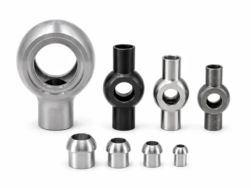
Wei Xing Machinery manufactures custom hydraulic cylinder components from approved production data. Each CNC hydraulic cylinder part is reviewed by its actual role, mating components, material, seals, loads, secondary processes and inspection plan.
Scope may cover metal parts only or agreed seals, bushings, welding and assembly. A worn sample can support review only after its wear, damage, repair history, hidden features and original interfaces are verified.
| Specification | Manufacturing and Review Basis |
|---|---|
| Product Type | Drawing-specific hydraulic cylinder machined parts; different parts perform different functions. |
| Component Functions | Pressure-chamber separation, rod guidance, seal retention, wear guidance, closure, load transfer, articulation, mounting, fluid or welded connection, as specified. |
| Typical Part Types | Pistons, rod glands, guides, heads, end caps, rods, rod ends, clevises, bushings, ports, bosses and retaining components. |
| Seal-System Basis | Exact seal manufacturer, part number, material, housing data, mating diameter, pressure direction, fluid and temperature. |
| Mechanical-Load Basis | Reviewed separately from hydraulic pressure using force direction, linkage, impact, pin fit, thread, fatigue, misalignment and safety factor. |
| Pressure-Boundary Basis | Confirmed only where the complete geometry, material, walls, retention, seals, ports, welds, cycles and assembly define a pressure boundary. |
| Mating Components | Cylinder tube, rod, seals, wear rings, pins, linkage, fittings, retention and mounting interfaces. |
| Body Materials | Carbon steel, alloy steel, stainless steel, or drawing-specified bronze and bearing materials for bushings; others after review. |
| Heat Treatment | Only when drawing-specified; material, treated area, distortion, machining allowance and inspection are reviewed without a common hardness. |
| Surface Finish | Drawing-specific finish selected by function; coating dimensions, masking, sliding, sealing, press-fit, thread and weld areas are reviewed. |
| Manufacturing Basis | Latest 2D drawing and revision, 3D model, mating data and verified sample. A sample alone cannot define original or hidden requirements. |
| Inspection Basis | Approved drawing and agreed sampling or full-inspection plan for specified part-level characteristics. |
| Complete-Cylinder Validation | The complete design and validation determine pressure, leakage, friction, stability, fatigue, temperature behavior and service life. |
| Delivery Scope | Metal parts, seals, bushings, welding, secondary processes, assembly and testing are included only as stated in the order. |
| Applications | OEM and replacement cylinder projects based on verified technical data; this page defines no common pressure or load rating. |
Drawing dimensions, material, thread, seal groove, bore, outside diameter, pin hole, surface, coating, heat-treatment result, weld preparation and other specified part-level characteristics.
Pressure capability, external and internal leakage, friction, stroke, speed, buckling, side load, cushioning, fatigue, temperature, service life and installation behavior.
Confirm outside diameter, length, shoulders, bore, rod connection and retention. The piston-to-bore relationship cannot be selected from a generic clearance.
Confirm the exact seal, groove, pressure direction and extrusion control. ISO 5597 or ISO 7425-1 may be referenced only when the approved drawing specifies the applicable housing; a similar appearance is not a design basis.
Confirm ring supplier, material, groove data, clearance, bearing length, side load, lubrication, temperature, fluid and alignment. A wear ring limits metal contact but does not remove all side load.
Confirm thread, nut, shoulder, locking and assembly requirements. A piston alone cannot determine complete-cylinder pressure.
Seal and wear-ring inclusion must be agreed separately. Seal standards describe selected housing dimensions, not the seal supplier’s material, design, pressure, speed, fluid, temperature or extrusion requirements.
| Feature | Primary Function | Required Information | Common Risk |
|---|---|---|---|
| Rod guide bore | Guides the rod | Rod diameter, guide material, clearance, alignment | Too little or too much clearance can impair the system |
| Rod seal housing | Controls hydraulic fluid along the rod | Exact seal and supplier housing data | A generic groove may damage or under-support the seal |
| Buffer seal housing | Conditions pressure before the main rod seal in specified systems | Complete seal arrangement and pressure direction | Treating it as a universal requirement |
| Wiper housing | Limits entry of external contamination | Exact wiper, rod and environment | A wiper does not replace the hydraulic rod seal |
| Guide-ring housing | Supports specified radial guidance | Ring data, side load and bearing length | Assuming guidance eliminates misalignment |
| Static seal | Seals gland-to-tube interface | O-ring or static seal data and mating body | Confusing a static groove with a reciprocating interface |
| Retaining feature | Mechanically locates the gland | Thread, flange, retaining ring or drawing-specific system | Using an undefined torque or retention capacity |
Rod guidance, dynamic rod sealing, contamination exclusion, static sealing and mechanical retention are separate functions. ISO 5597, ISO 7425-2 or ISO 6195 may be used only as specified by the approved order and seal-system data.
Review base material, diameter, length, unsupported extension, straightness, specified runout, thread, piston and rod-end connections.
Confirm surface condition, texture direction, defect limits, seal compatibility, lubrication, pressure, speed and coating. No common Ra value applies.
Precision turning, grinding, polishing, induction hardening, hard chrome or alternative wear/corrosion coating may be coordinated only when drawing-specified or project-reviewed.
Buckling and fatigue require rod diameter, extension, stroke, mounting, end condition, alignment, material, impact, side load and safety factor in the complete-cylinder analysis.
A metallic shine or polished appearance in a web image does not prove hardness, coating thickness, roughness, straightness or seal compatibility.
Confirm size, engagement, shoulder, locking, tension, compression, alternating load and mating rod.
Confirm pin diameter, fork spacing, lug thickness, edge distance, bearing area, articulation and angular misalignment.
Treat pin, bushing, housing and linkage as one interface. Confirm material, lubrication groove, grease hole, oscillation, speed, contamination and replacement. Installed bore may require final sizing or inspection.
Mechanical capacity depends on piston force, direction, inertia, shock, linkage, pin fit, thread, weld, side load, mounting, fatigue duty and safety factor—not pressure alone.
No universal press-fit interference or pin-hole clearance is defined here.
Geometry, port, thread, weld preparation, orientation reference, base material, machining allowance and part inspection.
Joint design, welding procedure, filler, heat input, preheat or post-weld requirements, distortion, post-weld machining, cleaning, weld inspection and pressure validation.
Supplying a machined weld-on component does not automatically include welding procedure qualification, assembly welding, post-weld heat treatment, nondestructive examination or complete-cylinder pressure validation. The order must define responsibility.
Available configurations depend on the approved drawing, mating parts, seal system, material, process and validation requirements; this list does not imply stock availability.
| Component Type | Primary Function | Sealing or Load Role | Critical Interfaces | Selection Considerations |
|---|---|---|---|---|
| Piston | Separates chambers and connects to rod | Dynamic seal and axial fluid-force transfer | Bore, seals, wear rings, rod retention | Seal system, clearance, deformation and validation |
| Rod gland | Guides rod and houses specified seals | Dynamic/static seal, guidance, retention | Rod, tube, seals, wiper, retention | Guidance, contamination and assembly |
| End cap / head | Closes or supports cylinder as drawn | May have pressure, seal, mounting roles | Tube, seals, port, retention | Wall, access, closure and test scope |
| Piston rod | Transfers motion through sliding seal | Axial load, buckling and sliding surface | Piston, gland, rod end | Extension, alignment, coating, fatigue |
| Rod end / clevis | Connects rod to machine linkage | Mechanical load and articulation | Thread, pin, linkage | Direction, impact, fit and fatigue |
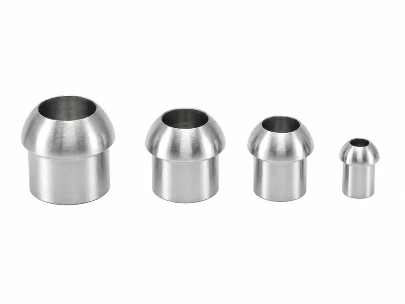
| Bushing | Provides pin bearing interface | Bearing, wear and oscillation | Pin and housing | Fit, lubrication, contamination, installed bore |
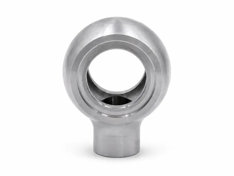
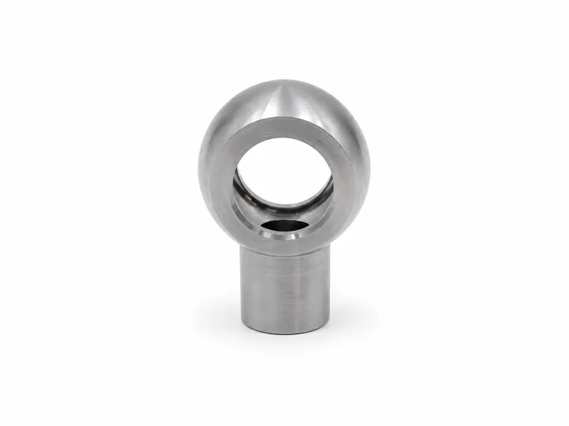
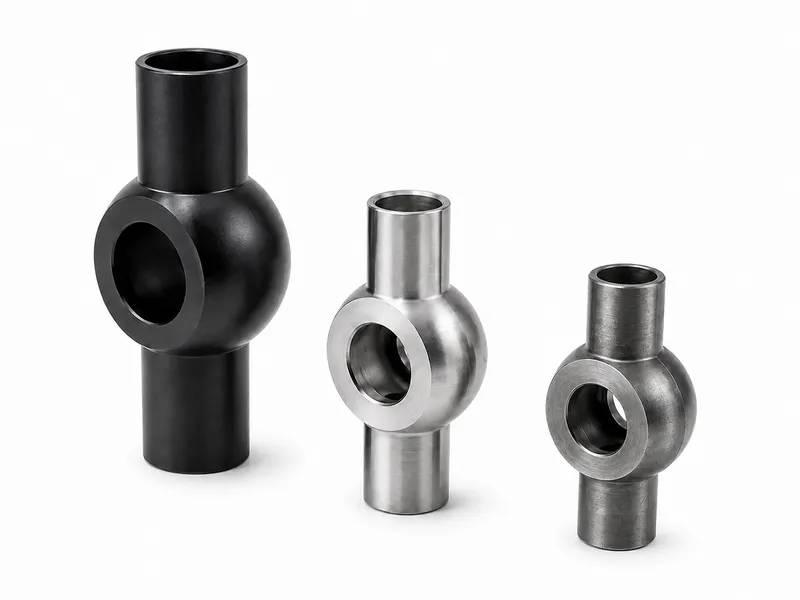
| Weld-on port / end | Provides connection or weldable structure | Pressure role only as complete design defines | Tube, fitting, weld joint | Weldability, distortion, inspection, validation |
Not every part uses every operation. Surface finishing and specified secondary processes can be coordinated according to material and order requirements.
Selected by drawing for appropriate pressure, load, machining, welding, fatigue and coating requirements.
Used only where its specified condition and subsequent heat treatment support the approved design.
Reviewed for grade, strength, fluid, corrosion exposure, finish, welding and mating compatibility.
Available for bushings when drawing-specified, with fit, lubrication, wear and installed-bore requirements confirmed.
Reviewed against application, mating parts and process requirements before manufacture.
Through, induction, case or local hardening, nitriding, stress relieving and tempering are applied only when specified; treated area, case depth, distortion, allowance, final grinding and inspection must be defined. Potential finishes include trivalent zinc, zinc-nickel, black oxide, applicable phosphating, natural stainless, compatible passivation and specified rod coatings. Grooves, sliding and press-fit surfaces, weld zones, threads, pin holes and grounding locations may need masking or different treatment. Coating dimensions affect fits, and finishing does not replace correct material, sealing, heat treatment, corrosion protection or lubrication design.
A worn replacement sample must not be copied by appearance alone. Wear, deformation, corrosion, coating loss, damaged grooves or threads, weld distortion, repairs and previous machining can obscure original dimensions. Confirm mating parts, seals, material, heat treatment, finish and complete-cylinder duty.
“Hydraulic cylinder part” or one appearance photograph is insufficient for an accurate quotation. Please identify function, current revision, mating components, seals, material, processes, pressure or mechanical loads, welding, inspection and delivery scope.
A complete cylinder may use a tube, piston rod, piston, rod gland or guide, heads or end caps, seals, wear rings, wipers, retention, ports, welds and mounting parts. Each component is reviewed by its own function.
No. Individual inspection confirms drawing characteristics only. Complete-cylinder pressure, internal and external leakage, stability, friction, fatigue and service life require validation of the complete assembly.
Provide the exact seal brand, part number and material, seal-manufacturer housing data, mating diameters, pressure direction, fluid, temperature and complete seal-system information.
For a pressure-boundary part, capability depends on material, geometry, effective wall thickness, seals, retention, mating parts, welds, temperature, cycles, assembly and complete-cylinder validation. One pressure cannot be assigned to the whole product category.
Confirm load direction, pin, fits, bearing area, thread engagement, articulation, lubrication, side load and fatigue duty together with the mating linkage.
No. Pressure capability depends on the complete joint geometry, base material, weld design and procedure, distortion control, inspection and complete-cylinder validation.
Drawing-specified carbon, alloy and stainless steels and specified bushing materials are reviewed by function. Compatible plating, oxide, phosphate, passivation, rod coating, heat treatment and other secondary processes can be coordinated as order requirements.
Send the latest drawing and revision, function, mating and seal or bushing data, material, heat treatment, finish, pressure or mechanical loads, welding and inspection scope, delivery scope and quantity. A photograph alone is insufficient.
Submit the latest part drawing, component function, mating dimensions, seal or bushing data, material, heat treatment, surface finish, load or pressure conditions, quantity and inspection requirements for manufacturing review and quotation.