
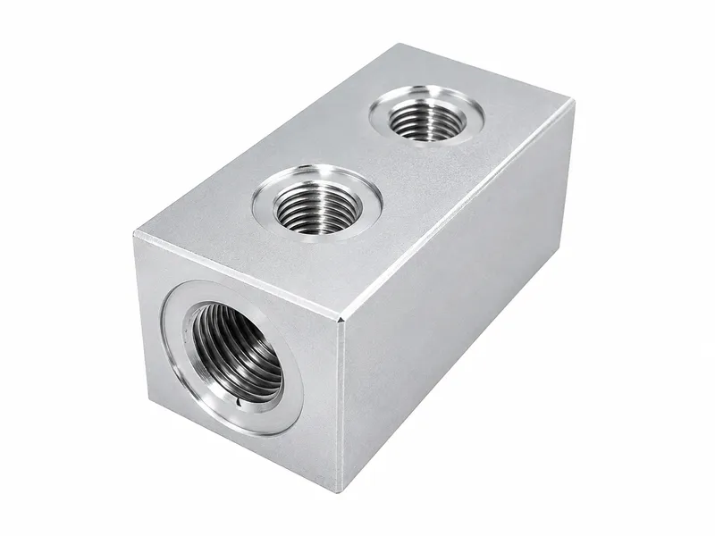
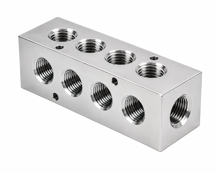
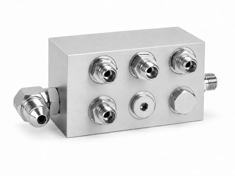
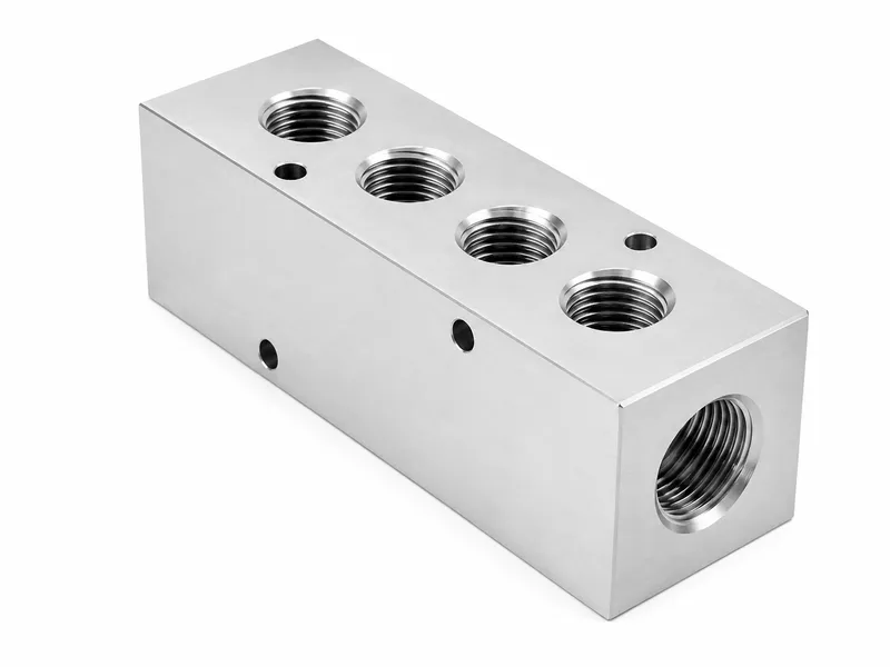
Manifold body provides
Internal passages, ports, valve cavities, mounting faces, sealing lands, closure locations, component interfaces and mechanical integration.
Hydraulic manifold precision machining for custom blocks manufactured to approved drawings and circuit information, integrating internal passages, ports, valve cavities, mounting faces and closure locations.
The body provides internal flow paths and mechanical interfaces for hydraulic components; actual pressure, direction and flow control is determined by installed valves, cartridges, plugs and the approved circuit. Port appearance or a physical sample alone cannot define the complete internal circuit. Passages, cross holes, cavities, effective wall sections, closures and machining datums must be drawing-controlled. Steel, stainless steel and aluminum blocks can be machined after review; this page defines no universal working pressure, cleanliness class or cavity compatibility.
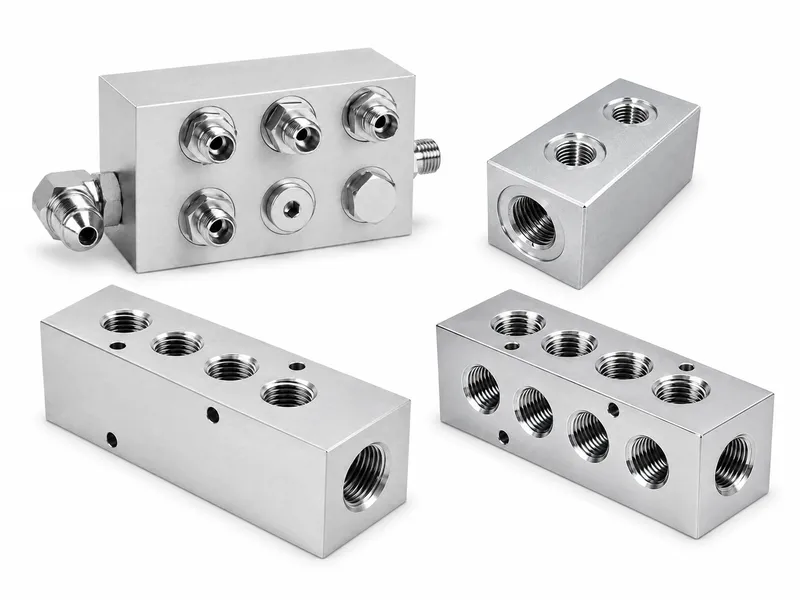
Wei Xing Machinery provides hydraulic manifold precision machining and custom manifold block manufacturing to approved 2D drawings, 3D models, schematics and mating-component data. A verified sample can support dimensional review, but hidden routing, depths, restrictions, closures and revisions require approved internal information.
| Product Type | Custom cross-drilled hydraulic manifold, hydraulic valve block, cartridge-valve block or hydraulic subplate as defined by the approved project. |
|---|---|
| Primary Function | Provides internal routing and component interfaces; installed components and the approved circuit determine control functions. |
| Circuit Definition Basis | Latest hydraulic schematic plus manufacturing drawing, port map, valve list and controlled revisions. |
| Internal Passage Features | Drawing-defined diameters, drilling directions, full-diameter and drill-point depths, intended intersections and wall sections. |
| Valve and Component Interfaces | Exact cavity, mounting-face, port, sealing and mating-component data required. |
| Passage Closure | Closure type, seat, retention, seal, depth, installation and test scope confirmed by drawing and order. |
| Body Materials | Carbon steel, stainless steel, aluminum alloy or other drawing-specified material after review. |
| Surface Finish | Material-compatible finish with specified masking and dimensional allowances. |
| Manufacturing Basis | Approved 2D drawing, 3D model, schematic and mating data; samples require verified internal information. |
| Inspection Basis | Approved drawing and agreed sampling or full-inspection plan; special verification only when specified. |
| Cleanliness Basis | Customer-defined process, particle limits, protection and packaging; no universal level applies. |
| Pressure / Validation Basis | Complete approved design, wall sections, components, closures, seals, conditions, assembly and validation; no category-wide rating. |
| Delivery Scope | Bare block, block with closures or fittings, partial assembly, or tested assembly only as stated in the order. |
| Applications | Drawing-specific manifolds for OEM, industrial, mobile, power-unit and test circuits. |
Internal passages, ports, valve cavities, mounting faces, sealing lands, closure locations, component interfaces and mechanical integration.
Pressure, flow and direction control, load holding, sequencing, relief, sensing, actuation, safety functions and overall behavior.
Defines functions, normal flow, control, drain and return paths, component logic and possible isolation.
Identifies specified ports; P, T, A, B, LS, drain, pilot, test and auxiliary are examples only and do not occur on every project.
Defines primary, secondary and tertiary datums, coordinate origin, dimensions, directions, hole positions and depths, cavities, threads, mounting faces, closures, tolerances and finish.
Confirm exact mating data plus drawing number, schematic, valve-list and 3D-model revisions. Remove superseded documents and never mix revisions.
Review direction, diameter, total depth, full-diameter depth, drill-point geometry, usable thread depth, functional cavity depth, sealing-land position and intended breakthrough.
Check unintended intersections and interference with adjacent passages, cavities, mounting holes, grooves and outside surfaces, plus tooling, deburring and cleaning access.
Review remaining material between passages, cavities, threaded or mounting holes and outside surfaces. No universal minimum is stated.
A smaller envelope is not automatically safe, a larger blank is not automatically higher rated, and fewer cross holes do not automatically make a circuit more reliable. Approved design and validation govern.
Confirm manufacturer, exact model, cavity designation and revision, sealing diameters, steps, angles, grooves, thread, depth, pilot and nose geometry, torque requirements and surface condition.
Confirm valve or subplate pattern, sealing lands, O-ring ports, bolt and dowel holes, reference edges, orientation and flatness. Name a standard only when the drawing specifies it.
Confirm each SAE straight-thread, ORFS, BSPP, BSPT, NPT, metric, flange or drawing-specific interface: standard, size, seal location, counterbore, spotface, groove, seat, usable depth and mating fitting.
Threaded, expansion, ball or staking, press-fit, drawing-specific sealed, or explicitly designed welded closure are possibilities—not universally suitable choices.
Confirm type, size, seat, retention, seal, depth, method, removal, pressure direction, material and coating compatibility, plus test requirement.
Quote bare blocks separately from blocks with installed closures. The order defines installation and testing; coating buildup can affect seats and threads.
Torque, sealant, press force, insertion depth, staking dimensions or welding parameters come from the approved design, supplier data and assembly procedure—not a generic webpage value.
Intersecting passages, cross and blind holes, threaded ports, cavities, grooves, mounting faces and breakthroughs require defined burr control.
Specify cleaning method, flushing medium, drying, particle limits, gravimetric analysis or cleanliness code when required.
Mechanical, thermal, abrasive-flow or brush deburring, manual or borescope inspection, flushing and particle inspection are used only when specified.
Orders may require caps, closed ports, clean packaging, controlled corrosion protection and protection of cavities and sealing faces; compatibility with the fluid must be reviewed.
Custom cross-drilled, cartridge-valve, directional-valve, multi-station, cylinder-control, power-unit, pump/motor interface and test manifolds.
Hydraulic subplates; aluminum, steel and stainless steel blocks; mobile-equipment blocks; and replacement blocks based on verified drawing and circuit data.
Available configurations depend on the approved schematic, drawing, mounted components, material, tooling and validation requirements; this list does not imply stock availability.
| Component Type | Primary Function | Internal Fluid Routing | Component Interface | Selection Considerations |
|---|---|---|---|---|
| Hydraulic manifold block | Integrates multiple passages, ports, cavities and mounting interfaces. | Complex, drawing-defined internal routing. | Specified valves, cartridges, closures and fittings. | Circuit, wall sections, cleanliness, assembly and validation. |
| Hydraulic valve body | Built around a specific spool, seat, cavity or valve function. | Routes fluid for its defined valve geometry. | Internal valve elements and external ports. | Valve geometry, sealing and operating requirements. |
| Hydraulic subplate | Connects a specified valve mounting face to external ports. | Routing focused on the defined mounting interface. | Valve face, seals, bolts and ports. | Pattern, orientation and mating valve data. |
| Rigid adapter | Joins two or more discrete interfaces. | Limited routing rather than a complex integrated circuit. | Threaded, flanged or drawing-specific ends. | Interface standards and sealing method. |
| Welded tube assembly | Routes fluid through rigid tubing and welded features. | External rigid flow path. | Welded fittings, flanges and equipment ports. | Route, heat input, inspection and cleanliness. |
| Hydraulic hose assembly | Provides a flexible connection. | Fluid travels through the complete hose assembly. | Hose ends and mating ports. | Hose, fittings, routing and assembly validation. |
CNC milling; CNC drilling and suitable deep-hole drilling; boring and reaming; internal and external threads; spotfaces and counterbores; valve and cartridge cavities to approved drawings; mounting faces, sealing lands and specified O-ring grooves; cross passages, plug seats and dowel holes; precision hole positioning; deburring, cleaning and passage protection; dimensional and specified coordinate inspection; coordination of material-compatible finishing.
Surface finishing can be coordinated according to material and order requirements. Not every operation applies to every manifold block.
Review the specified grade, effective wall sections, service conditions and compatible finish.
Review fluid, corrosion, machinability and surface requirements.
Review alloy and temper, wall sections, threads, cavities, plugs, cyclic loads, temperature, corrosion, mounted loads, weight and validation.
Use only after drawing and project review.
Possible finishes include trivalent zinc, zinc-nickel, black oxide or applicable phosphating for steel; anodizing or conversion coating for aluminum; and natural finish or specified compatible passivation for stainless steel. Cavities, mounting and sealing faces, O-ring grooves, precision bores, threads and plug seats may need masking or separate requirements. Coating affects fits and later closure or valve assembly. Heat treatment, grinding, honing, lapping or precision matching is supplied only when drawing-specified; process sequence and distortion require review.
Drawing and revision review; schematic and valve-list review; material documentation; datum and coordinate review; port identification and thread inspection; cavity and mounting-face inspection; passage diameter, full-diameter depth and drill-point review; intersection and approved wall-section review; plug seats and sealing grooves; cross-hole deburring; masking review; and dimensional qualification. Coordinate measurement, hidden-passage or cleanliness inspection, passage/flow checks, leak or proof-pressure, functional, fatigue, pressure-cycle or plug-retention tests are performed only when specified. Sampling or full inspection follows the agreed plan; dimensional acceptance alone does not prove the circuit.
Hydraulic power units; mobile construction and agricultural machinery; industrial automation; presses and forming equipment; lifting and material handling; machine-tool hydraulics; cylinder, pump and motor control circuits; OEM equipment; and custom cartridge-valve circuits. Replacement manifolds require verified internal routing, valves, closures, ports and revision data—not visual copying of an old block.
Wei Xing Machinery manufactures to customer-approved drawings, schematics, models, verified samples and order requirements and can review manufacturability; it cannot infer missing circuit functions from appearance. The customer or system designer is responsible for circuit function, valve selection, control logic, system safety, consistent document revisions, operating pressure, cycles, fatigue, fluid, temperature and complete-system validation. The order must define supply and installation of closures, valves, fittings, O-rings, coils and sensors, and any cleanliness, particle inspection, pressure or functional testing. Sample appearance alone cannot define hidden routing, depths, restrictions, wall sections or revisions. Final acceptance follows approved documents and the agreed inspection plan.
A hydraulic manifold block is a machined body that provides drawing-defined internal passages, ports, valve cavities, mounting faces, sealing lands and closure locations for specified hydraulic components.
No. The block body provides passages and mounting interfaces; actual pressure, direction and flow control depends on the installed valves, cartridges, plugs and approved circuit design.
The schematic defines hydraulic logic, connections and component functions. The part drawing and model define machining geometry, datums, hole depths, cavities, tolerances and closure locations; neither an external sample nor a schematic alone defines every manufacturing detail.
Drawing-specified threaded, expansion, press-fit, staked or other closures may be used after reviewing the seat, retention, seal, installation depth, pressure direction, material, coating, maintenance and test requirements. The order must define installation scope.
They are confirmed from the exact valve model, supplier data, cavity drawing and revision, and the customer-approved drawing. A thread match or similar appearance alone does not establish compatibility.
Allowable conditions depend on the complete approved design, effective wall sections, material, passages, cavities, ports, closures, mounted components, seals, temperature, fluid, pressure cycles, assembly and validation requirements. This page does not assign one category-wide rating.
Deburring, cleaning, borescope inspection, flushing or particle inspection is defined by the drawing, order and inspection plan. Hidden intersections need specific control, and no single cleanliness level is promised for every block.
Provide the latest schematic, part drawing and revisions, model if available, port map, valve and cavity data, passage and closure details, material, finish, cleanliness, delivery scope, operating conditions, quantity, inspection and validation requirements.
Submit the latest manifold drawing, hydraulic schematic, valve and cartridge data, port and passage details, closure requirements, material, quantity, cleanliness and validation requirements for manufacturing review and quotation.