
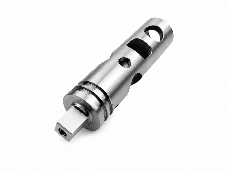
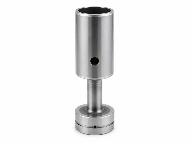
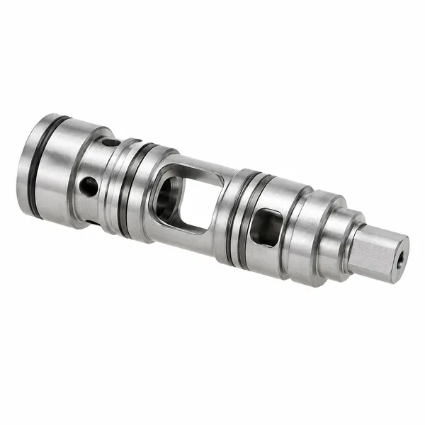
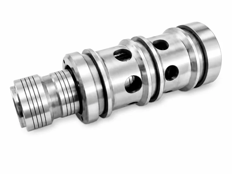
Valve spool
Moves axially; lands, grooves and metering edges work with a bore or sleeve to open, close or meter ports. It does not establish complete-valve performance.
Drawing-specific precision valve spools, matching sleeves and hydraulic pistons manufactured for hydraulic control, actuation and motion-control assemblies.
Spools, sleeves and pistons are precision parts with different functions. Lands, grooves, metering edges, notches and radial holes must be reviewed with the mating body or sleeve, while spool outside diameters and sleeve bores must be confirmed as a fitted system. Dimensional conformity of one spool does not establish complete-valve leakage, flow, hysteresis, response, pressure or life; piston seal grooves and spool metering features require different design rules. Manufacturing review may use approved drawings, 3D models, mating-part data and verified samples. This page defines no universal clearance, pressure, leakage, roughness, hardness or flow performance.
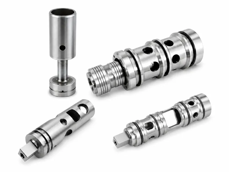
As a hydraulic valve spool manufacturer, we machine control valve spools, sleeves, hydraulic pistons and other precision cylindrical components to approved designs. Component identity, function, mating method and inspection scope are confirmed before quotation; plungers, poppets and shaft-type parts are not called spools merely because they are cylindrical.
Drawing-specific CNC valve spool machining can cover lands, grooves, radial holes, slots, sleeve bores and piston seal grooves. The route depends on geometry, datums, material, heat treatment, coating, quantity, tolerances and surface requirements.
| Specification | Drawing-Specific Basis |
|---|---|
| Product Type | Drawing-specific spools, sleeves, hydraulic pistons and other precision cylindrical parts with distinct functions |
| Primary Functions | Spools establish switching or metering relationships; sleeves provide fitted bores and ports; pistons separate pressure chambers and transfer force |
| Typical Part Types | Control and metering spools, sleeves, bushings, hydraulic pistons, plungers and shaft-type parts |
| Mating-System Basis | Spool outside diameters and sleeve or body bores reviewed from the same approved design |
| Critical Geometry | Land diameters and widths, grooves, axial locations, holes, slots, bores, seal grooves and datum relationships |
| Fit and Clearance Basis | Defined by function, mating parts, material, temperature, coating, fluid and validation; no universal website value |
| Metering-Edge Basis | Functional-edge location, profile, direction, permitted burr and edge break follow approved drawings |
| Radial-Hole and Slot Features | Confirm profile, quantity, angular and axial position, intersections, internal/external edges, cleaning and inspection |
| Body Materials | Carbon steel, alloy steel, stainless steel, drawing-specified hardened steel, specified sleeve or bearing materials, and reviewed project materials |
| Heat Treatment | Only as drawing-specified, coordinating treatment area, hardness, case depth, distortion allowance, final grinding and inspection |
| Surface Finish | Confirm parameter, direction, evaluation length, lay, waviness, defects, coating condition and mating surface separately |
| Manufacturing Basis | Review from latest 2D drawing, 3D model, mating-part data and verified sample; a sample alone cannot define original fit or metering geometry |
| Inspection Basis | Agreed inspection of dimensions, form, position, edges, surface, hardness, coating, fit group or cleanliness |
| Cleanliness Basis | Order-defined cleaning, residual-particle limit, preservation medium, protective caps and packaging |
| Functional Validation | No universal pressure, flow, leakage, life or interchangeability is defined; complete performance requires assembly validation |
| Delivery Scope | Independent interchangeability, grouped or selective fit, or matched identification follows the approved design and order |
| Applications | Hydraulic control valves, actuators, mobile machinery, industrial systems and replacement work based on verified data |
Moves axially; lands, grooves and metering edges work with a bore or sleeve to open, close or meter ports. It does not establish complete-valve performance.
Provides a precision internal bore, windows or ports supporting spool fit and port timing. It may be press-fitted or retained, and installation can affect the bore.
Separates pressure chambers, supports seals and wear rings, transfers load and connects to a rod or shaft under separate seal-system requirements.
Spool lands and sleeve bore, windows, ports, axial position and working stroke are reviewed from the same approved design. Equal nominal diameter does not prove compatibility.
Confirm diameter variation, taper, cylindricity, roundness, straightness, coating allowance, thermal expansion, measurement temperature, lubrication, viscosity and functional clearance.
Press fitting can change the final sleeve bore. Preserve identity for matched supply; independent interchangeability needs tolerance design and validation. One part report cannot independently confirm function.
| Feature | Possible Function | Required Drawing Information | Inspection Focus |
|---|---|---|---|
| Land diameter | Port coverage/opening, metering, guidance, communication, balancing, location or drawing-defined function | Size, position, radius or chamfer, axial spacing, port relationship, neutral position and permitted edge break | Size, datum relationship, profile, burr, surface damage and relationship to the relevant window |
| Land width | Port coverage/opening, metering, guidance, communication, balancing, location or drawing-defined function | Size, position, radius or chamfer, axial spacing, port relationship, neutral position and permitted edge break | Size, datum relationship, profile, burr, surface damage and relationship to the relevant window |
| Groove diameter | Port coverage/opening, metering, guidance, communication, balancing, location or drawing-defined function | Size, position, radius or chamfer, axial spacing, port relationship, neutral position and permitted edge break | Size, datum relationship, profile, burr, surface damage and relationship to the relevant window |
| Groove width | Port coverage/opening, metering, guidance, communication, balancing, location or drawing-defined function | Size, position, radius or chamfer, axial spacing, port relationship, neutral position and permitted edge break | Size, datum relationship, profile, burr, surface damage and relationship to the relevant window |
| Shoulder position | Port coverage/opening, metering, guidance, communication, balancing, location or drawing-defined function | Size, position, radius or chamfer, axial spacing, port relationship, neutral position and permitted edge break | Size, datum relationship, profile, burr, surface damage and relationship to the relevant window |
| Metering edge | Port coverage/opening, metering, guidance, communication, balancing, location or drawing-defined function | Size, position, radius or chamfer, axial spacing, port relationship, neutral position and permitted edge break | Size, datum relationship, profile, burr, surface damage and relationship to the relevant window |
| Notch or slot | Port coverage/opening, metering, guidance, communication, balancing, location or drawing-defined function | Size, position, radius or chamfer, axial spacing, port relationship, neutral position and permitted edge break | Size, datum relationship, profile, burr, surface damage and relationship to the relevant window |
| Axial hole | Port coverage/opening, metering, guidance, communication, balancing, location or drawing-defined function | Size, position, radius or chamfer, axial spacing, port relationship, neutral position and permitted edge break | Size, datum relationship, profile, burr, surface damage and relationship to the relevant window |
| Radial hole | Port coverage/opening, metering, guidance, communication, balancing, location or drawing-defined function | Size, position, radius or chamfer, axial spacing, port relationship, neutral position and permitted edge break | Size, datum relationship, profile, burr, surface damage and relationship to the relevant window |
| End feature | Port coverage/opening, metering, guidance, communication, balancing, location or drawing-defined function | Size, position, radius or chamfer, axial spacing, port relationship, neutral position and permitted edge break | Size, datum relationship, profile, burr, surface damage and relationship to the relevant window |
Confirm diameter or profile, quantity, angular spacing, axial position, orientation and relevant flow direction.
Radial-to-axial hole intersections are critical areas; a clean visible outer edge does not prove the internal intersection is acceptable.
Slot, window or orifice edges may be functional. Deburring must not alter approved metering geometry.
Controlled manual deburring, brushing, abrasive flow, suitable thermal deburring, ultrasonic cleaning, borescope or magnified inspection apply only when selected by drawing and order.
| Control | What It Evaluates | Why It Matters | Information to Confirm |
|---|---|---|---|
| Roundness | Deviation of one cross-section from an ideal circle | Affects fit, motion, sealing or port relationship and is reviewed by function | Drawing datum, inspection method, process stage and reinspection after heat treatment or coating |
| Cylindricity | Combined form of the entire cylindrical surface | Affects fit, motion, sealing or port relationship and is reviewed by function | Drawing datum, inspection method, process stage and reinspection after heat treatment or coating |
| Straightness | Straight condition of an axis or surface generator | Affects fit, motion, sealing or port relationship and is reviewed by function | Drawing datum, inspection method, process stage and reinspection after heat treatment or coating |
| Runout | Variation during rotation relative to a specified datum | Affects fit, motion, sealing or port relationship and is reviewed by function | Drawing datum, inspection method, process stage and reinspection after heat treatment or coating |
| Coaxial relationship | Axis relationship between different cylindrical features | Affects fit, motion, sealing or port relationship and is reviewed by function | Drawing datum, inspection method, process stage and reinspection after heat treatment or coating |
| Axial land position | Land location relative to axial datum and ports | Affects fit, motion, sealing or port relationship and is reviewed by function | Drawing datum, inspection method, process stage and reinspection after heat treatment or coating |
Drawing dimensions, form, surface, coating allowance, fit group, pair marking, burr condition, cleanliness and agreed part-level inspection.
Actual internal leakage, movement force, pressure drop, flow curve, hysteresis, response, temperature and contamination behavior, endurance and complete function.
A piston differs from a spool and may support elastomeric seals, wear rings or guide rings. Its OD relationship to a cylinder, valve bore or sleeve follows the complete design.
Match the exact seal maker, part number, material, mating diameter, pressure direction, extrusion gap, backup ring, temperature, fluid, speed and installation method.
Clarify whether seals are supplied. A component page cannot define piston pressure capability, and a piston seal groove is not a spool metering groove.
Use pre-grinding allowance, heat-treatment distortion, geometry and datums to select OD or cylindrical grinding, suitable centerless grinding, or sleeve internal grinding or honing.
After grinding, inspect final diameter, form, land position, surface texture, defects and edge protection; clean after abrasive processing and recheck fit.
Brighter polish is not inherently better, and lapping or honing is not required for every project. Later coating can change size; drawing parameters, not visual gloss, govern acceptance.
Reviewed for wear, strength, treatment and corrosion requirements.
Reviewed with fatigue, heat treatment, grinding and coating.
Reviewed for fluid, corrosion, wear and mating material.
Used only with defined condition, treatment area, hardness and distortion requirements.
Bronze or another material is used only when the approved design defines it.
Reviewed for temperature, magnetic needs, contamination and quantity.
Only when drawing-specified: confirm area, hardness, case depth, distortion, allowance, final grinding, thread/hole protection and inspection.
Confirm area, masking, dimensional allowance, final-size basis, post-finishing, adhesion and inspection, plus edge and hole protection.
Protect precision fits from dents, scratches, corrosion and particles; clean radial holes, grooves and sleeve windows.
Maintain paired-part identity. Protective caps, individual wrap, clean bags or VCI are order-defined.
Preservation media must suit fluid, seals, coating, cleanliness and later assembly. No common particle-cleanliness level is promised.
Directional valve spools when drawing-specified, proportional valve spools when drawing-specified, control spools, metering spools, pressure-control spool components, spool-and-sleeve pairs, hollow sleeves, valve bushings, piston-style valve components, hydraulic and grooved pistons, radial-hole spools, slotted or windowed sleeves, precision plungers and drawing-specific cylindrical valve parts.
| Component Type | Primary Function | Main Mating Interface | Critical Geometry | Validation Focus |
|---|---|---|---|---|
| Valve spool | Port switching or metering with mating features | Approved bore, sleeve, cylinder, seat, rod or mechanism | Function-defined diameter, form, position, ends, holes, grooves or seal features | Part inspection and order-defined assembly validation |
| Valve sleeve | Provides bore, ports and installation interface | Approved bore, sleeve, cylinder, seat, rod or mechanism | Function-defined diameter, form, position, ends, holes, grooves or seal features | Part inspection and order-defined assembly validation |
| Hydraulic piston | Pressure-chamber separation and axial force transfer | Approved bore, sleeve, cylinder, seat, rod or mechanism | Function-defined diameter, form, position, ends, holes, grooves or seal features | Part inspection and order-defined assembly validation |
| Plunger | Linear movement or pressure action | Approved bore, sleeve, cylinder, seat, rod or mechanism | Function-defined diameter, form, position, ends, holes, grooves or seal features | Part inspection and order-defined assembly validation |
| Poppet | Opens or closes flow at a seat | Approved bore, sleeve, cylinder, seat, rod or mechanism | Function-defined diameter, form, position, ends, holes, grooves or seal features | Part inspection and order-defined assembly validation |
| Custom shaft-type component | Transfers motion, locates or connects | Approved bore, sleeve, cylinder, seat, rod or mechanism | Function-defined diameter, form, position, ends, holes, grooves or seal features | Part inspection and order-defined assembly validation |
Precision CNC turning; CNC milling where required; drilling; axial, radial and cross-hole machining; slots and windows; annular grooves; lands and shoulders; approved metering profiles; internal and external threads; precision boring and sleeve bores; drawing-specified OD and cylindrical grinding; suitable specified centerless grinding; specified internal grinding, honing, polishing or superfinishing; piston seal grooves; controlled and internal-intersection deburring; cleaning; dimensional and specified surface inspection; specified matched-fit or group inspection; and coordination of heat treatment and material-compatible coatings.
Review drawing number and revision, component function, mating body/bore/sleeve, material and documents, and specified heat-treatment or coating records. Inspect land and groove dimensions, axial position, overall length, radial-hole size/position/orientation, slot or window profile, metering edges and internal-intersection burrs; specified roundness, cylindricity, straightness, runout, coaxial relationship, finish, hardness and coating thickness; sleeve bore, specified fit, group classification, pair identity, cleanliness, final protection and packaging. Sampling or full inspection follows the agreed plan; complete-valve tests occur only when expressly ordered.
Applications include hydraulic directional, pressure-control and flow-control valves; drawing-specified proportional controls; cartridge and modular components; mobile, agricultural and construction equipment; industrial systems and power units; motion-control equipment; hydraulic cylinder or actuator pistons; OEM valve assemblies; replacements based on verified drawings and mating data; and custom valve development. Replacement parts cannot be copied from worn appearance alone: verify the original mate, metering edges, port relationships, material, treatment, coating, clearance and complete-valve conditions.
A hydraulic valve spool is a drawing-specific moving part whose lands, grooves, metering edges, notches, holes and axial position work with a bore or sleeve to switch or meter paths. Complete-valve performance still requires assembly validation.
A spool uses lands, grooves and metering edges with a bore or sleeve; a sleeve provides the precision bore, windows or ports; a hydraulic piston normally separates pressure chambers, supports seals and transfers axial force. Similar appearance does not make them interchangeable.
Not every project requires paired manufacture. Independent interchangeability, tolerance grouping, selective assembly, lapping or paired identification is defined by the approved design and inspection plan.
Clearance is determined by valve function, diameters, form error, temperature, materials, coating, fluid, viscosity, leakage and movement requirements. This page provides no universal value.
Lands, metering edges, radial holes and sleeve ports jointly affect opening relationships and flow paths, but complete flow performance must be validated in the assembled condition.
Drawing-specific OD, cylindrical or suitable centerless grinding, internal grinding or honing, polishing, hardening, nitriding, carburizing, tempering, stress relief and material-compatible coatings may be reviewed. Areas, allowances, final sizes and inspection must be coordinated; no process applies to every part.
Not directly. A used sample may be worn, polished, distorted, corroded or missing coating, so measured values are not automatically original design values. Confirm original function, mate, material, treatments, critical metering features and acceptance responsibility.
Provide the latest 2D drawing and revision, available 3D model, function, mating bore or sleeve, lands/grooves, metering edges, holes/slots, clearance and fitting method, material, treatments, form/finish, cleanliness/packaging, inspection/validation scope, quantity and production stage.
Submit the latest drawing, mating bore or sleeve data, lands, grooves, metering edges, radial holes, fit requirements, material, heat treatment, coating, quantity and inspection requirements for manufacturing review and quotation.