
Hydraulic Valve Machining & Custom Valve Bodies
Precision CNC hydraulic valve machining for custom valve bodies with spool bores, cartridge cavities, threaded ports, internal oil passages, sealing faces and mounting features, manufactured to customer drawings, 3D models or approved samples.
Wei Xing Machinery provides hydraulic valve machining services for custom valve bodies used in directional, pressure-control, flow-control, check and cartridge valve assemblies. We machine critical bores, cavities, ports, sealing interfaces and internal passages according to customer drawings and agreed inspection requirements.
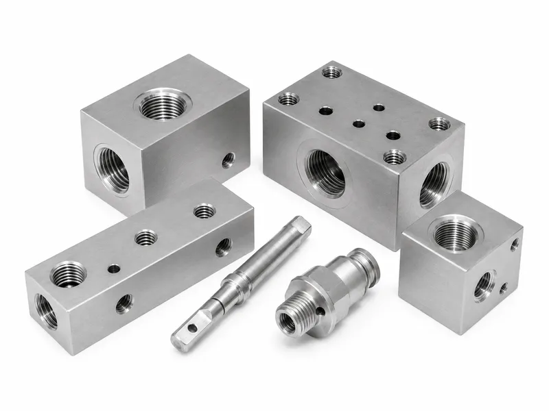
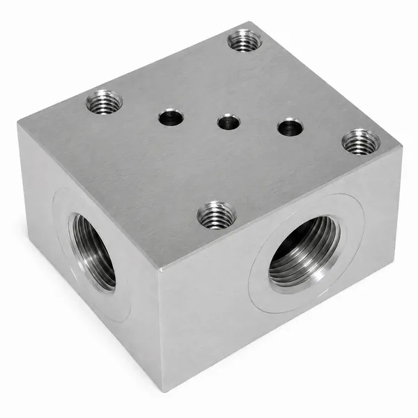
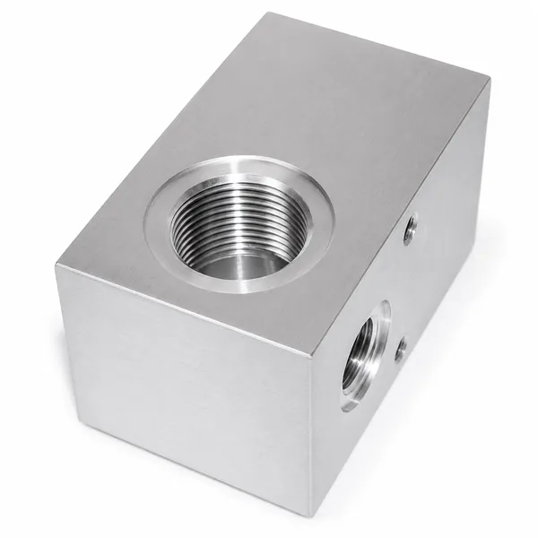
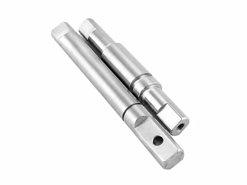
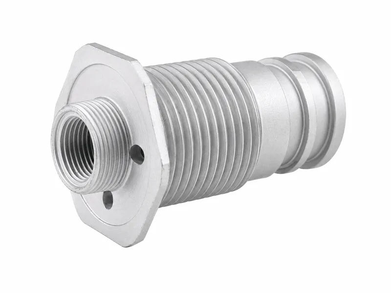
Hydraulic Valve Machining Services
Wei Xing Machinery provides custom hydraulic valve body machining for directional, pressure-control, flow-control, check and cartridge valve assemblies. We machine valve bores, cartridge cavities, threaded ports, internal oil passages, sealing faces, O-ring grooves and mounting features from customer drawings, 3D models or approved samples.
Machining processes may include CNC milling, drilling, tapping, precision boring, reaming, hydraulic valve bore finishing, cavity machining, cross-hole deburring, cleaning and drawing-specified secondary operations. Material, tolerances, surface finish and inspection requirements are reviewed for each project before quotation.
Hydraulic Valve Body Key Specifications
| Product Type | Drawing-specific hydraulic valve bodies for functional bores, cavities, ports, passages, sealing interfaces and mounting features |
|---|---|
| Materials | Carbon steel, stainless steel and aluminum alloy; alloy steel when specified; cast iron or ductile iron when project requirements are defined |
| Manufacturing Process | CNC milling, drilling, tapping, precision boring or reaming, hydraulic valve bore finishing, valve spool bore machining, cartridge cavity machining, hydraulic valve port machining, internal oil passage machining, deburring, cleaning and drawing-specified secondary processing |
| Functional Features | Direct spool bores, sleeve and bushing bores, cartridge cavities, poppet seats, threaded ports, cross-drilled passages, sealing lands, O-ring grooves, plug locations and mounting faces when specified |
| Surface Treatment | Material-compatible external finishes such as trivalent zinc plating, zinc-nickel coating, black oxide, phosphating, anodizing, conversion coating, passivation or natural stainless-steel finish, subject to drawing and order requirements |
| Inspection Basis | Critical features are controlled according to the approved drawing, mating components and agreed inspection plan |
| Heat Treatment | Applied only when specified according to material, wear interface, mating component and valve design |
Hydraulic Valve Body Comparison
| Component Type | Main Function | Design Focus | Typical Use |
|---|---|---|---|
| Hydraulic Valve Body | Houses or interfaces with moving or sealing valve elements | Spool bores, sleeve fits, poppet seats or cartridge cavities tied to a specific valve assembly | Directional, pressure-control, check, flow-control or cartridge valve assemblies |
| Hydraulic Manifold Block | Integrates passages and mounting interfaces for multiple components | Circuit porting, cavity locations and mounted valve interfaces | Compact hydraulic circuits and mounted valve groups |
| Direct Spool-Bore Valve Body | The spool moves directly in a drawing-specified precision bore | Bore geometry, surface condition and mating spool fit | Valve assemblies designed with direct body-to-spool fit |
| Sleeve-Type Valve Body | A separate sleeve or bushing is installed | Body bore controls sleeve position and retention | Valves using replaceable or fitted sleeves |
| Cartridge Valve Body | A drawing-specified cavity receives a compatible cartridge valve | Cavity form, sealing positions, porting and cartridge data | Cartridge valve assemblies |
| Poppet / Seat Valve Body | Seat geometry and guide features match the specified poppet or seat component | Sealing angle, coaxial relationship and contact position | Check, relief or poppet-type valves |
Critical Features We Machine
Direct Spool Bores
Valve spool bore machining follows the drawing-defined datum and mating spool requirements.
Sleeve and Bushing Bores
Body bores support sleeve or bushing location, retention and fit requirements.
Cartridge Valve Cavities
Cartridge cavity machining controls the cavity form, port windows and seal locations when specified.
Poppet Seats
Seat features are machined to match the specified poppet, seat or sealing component.
Threaded Hydraulic Ports
Hydraulic valve port machining covers drawing-specified threaded and sealing interfaces.
Cross-Drilled Oil Passages
Passages and intersections are machined from defined datums to connect the intended circuits.
Sealing Lands and O-Ring Grooves
Sealing surfaces and grooves are protected or finished according to drawing requirements.
Plug Locations and Mounting Faces
Closure points, bolt patterns and mounting faces are produced to match assembly interfaces.
CNC Machining Capabilities for Hydraulic Valve Bodies
The actual process route is selected according to the approved drawing and project review; not every order requires every operation.
Material and Blank Verification
Confirm material, grade, blank form and drawing notes before machining.
Datum and Machining-Plan Review
Review datums and operation sequence for bores, cavities, ports, passages and mounting features.
CNC Milling and Drilling
Machine external geometry, mounting faces, port locations and cross-drilled features.
Precision Boring, Reaming and Valve Bore Finishing
Hydraulic valve bore finishing may use precision boring, reaming and drawing-specified secondary finishing methods to control functional bore geometry and surface condition.
Spool Bore and Sleeve Bore Machining
Machine direct spool bores or sleeve bores according to mating component requirements.
Cartridge Cavity Machining
Produce drawing-specified cartridge cavities and related port windows.
Poppet Seat and Sealing-Interface Machining
Prepare seats, sealing lands and O-ring interfaces for the defined valve design.
Threaded Port Machining
Machine threaded hydraulic ports and sealing faces to the specified interface standard.
Internal Oil Passage Machining
Create internal oil passages, intersections and closure locations from the approved drawing.
Cross-Hole Deburring
Remove harmful burrs from accessible cross holes and internal intersections based on the agreed inspection plan.
O-Ring Groove and Mounting-Face Machining
Machine grooves, faces and bolt patterns used for sealing and installation.
Inspection and Secondary Operations
Drawing-specified inspection, cleaning and secondary operations are reviewed before quotation.
Materials and Surface Finish Options
Material grade, blank form, heat treatment, coating and protected functional surfaces are reviewed according to the drawing, operating environment and mating valve components.
Available material options may include carbon steel, stainless steel, aluminum alloy, alloy steel when specified, and cast iron or ductile iron when project requirements are defined.
Surface finish options may include trivalent zinc plating, zinc-nickel coating, black oxide, phosphating, anodizing, conversion coating, passivation and natural stainless-steel finish, subject to material compatibility and order requirements.
Hydraulic Valve Body Quality Control
Material and Drawing Verification
Review material, revision, notes and order requirements before production.
Datum and Critical-Feature Review
Confirm the datum scheme for functional bores, cavities, ports and sealing faces.
Thread and Cavity Inspection
Inspect threads, cavity forms, seal locations and thread depths according to the drawing.
Bore and Sealing-Interface Inspection
Check functional bores, sealing lands and mounting interfaces based on the agreed inspection plan.
Port-Position and Passage Verification
Verify port positions, passage relationships and closure locations.
Cross-Hole and Internal-Burr Inspection
Review cross holes, blind holes and internal intersections for harmful burrs.
Cleaning and Surface Protection
Apply drawing-specified cleaning requirements and protect functional surfaces after cleaning.
Final Inspection and Fit Review
Complete final dimensional inspection; mating-component fit review is included only when it is part of the order scope.
Applications
Directional Valve Assemblies
Bodies for specific spool, sleeve or actuator-interface designs.
Pressure-Control and Check Valves
Bodies with drawing-specified poppet, seat, spring, plug and port relationships.
Flow-Control and Cartridge Valves
Custom hydraulic valve components with machined cavities and related sealing locations.
OEM Hydraulic Equipment
OEM hydraulic valve body parts for mobile, industrial and automation equipment.
Information Required for Quotation
1. Drawings and models
Latest 2D drawings, 3D models, hydraulic schematics and revision information.
2. Valve design
Valve type, intended function and whether the design uses a direct spool bore, sleeve, cartridge cavity or poppet seat.
3. Mating components
Spool, sleeve, cartridge, poppet, seat, spring, plug and seal information where applicable.
4. Material and finish
Material grade, blank form, heat treatment, coating and areas that must remain uncoated.
5. Critical requirements
Functional bores, fits, clearances, surface finish, threads, ports, passages, sealing faces, deburring and cleanliness requirements.
6. Order information
Prototype or production quantity, inspection requirements, testing scope, samples and required documentation.
Engineering Responsibility
Frequently Asked Questions
What is a hydraulic valve body?
A hydraulic valve body is a machined housing that provides bores, cavities, ports, passages, sealing interfaces and mounting features for a specific valve design.
What hydraulic valve body designs can you machine?
We can review drawing-specific direct spool-bore, sleeve-type, cartridge-cavity and poppet or seat valve bodies when mating component data and acceptance criteria are provided.
Which materials are available?
Common options include carbon steel, stainless steel and aluminum alloy. Alloy steel, cast iron or ductile iron can be reviewed when project requirements are defined.
What information is required for quotation?
Please provide current drawings, models, schematics, revision data, mating components, material and finish requirements, critical features, quantities, inspection scope and samples when available.
How are valve bores, ports and internal passages inspected?
Inspection follows the drawing and agreed inspection plan, covering critical bores, cavity features, port positions, passage relationships, sealing interfaces and final dimensions.
How are hydraulic valve bores finished?
Valve bore finishing is selected from the approved drawing and mating-component requirements. Depending on the design, the process may use precision boring, reaming or another drawing-specified finishing operation, followed by inspection of the required bore geometry and surface condition.
How are cross-hole burrs and cleanliness controlled?
Cross-hole deburring and cleaning requirements are reviewed by drawing or order scope, with functional surfaces protected after specified cleaning.
Are hydraulic valve bodies pressure or function tested?
Bare-body inspection confirms machining features only. Pressure, leakage, flow and function testing must be validated on the completed valve assembly when required by the customer design and test plan.
How is a valve body different from a hydraulic manifold block?
A valve body directly houses or interfaces with moving or sealing valve elements; a manifold block primarily integrates passages and mounting interfaces for multiple hydraulic components.
Need a Quote for This Product?
Tell us your requirements and available technical information so we can review the project and prepare a quotation.