
Controlling drawing
Confirm drawing number, latest approved revision, approval date where applicable, dimensions, tolerances, GD&T, datums, threads, roughness, material, treatment notes and inspection requirements.
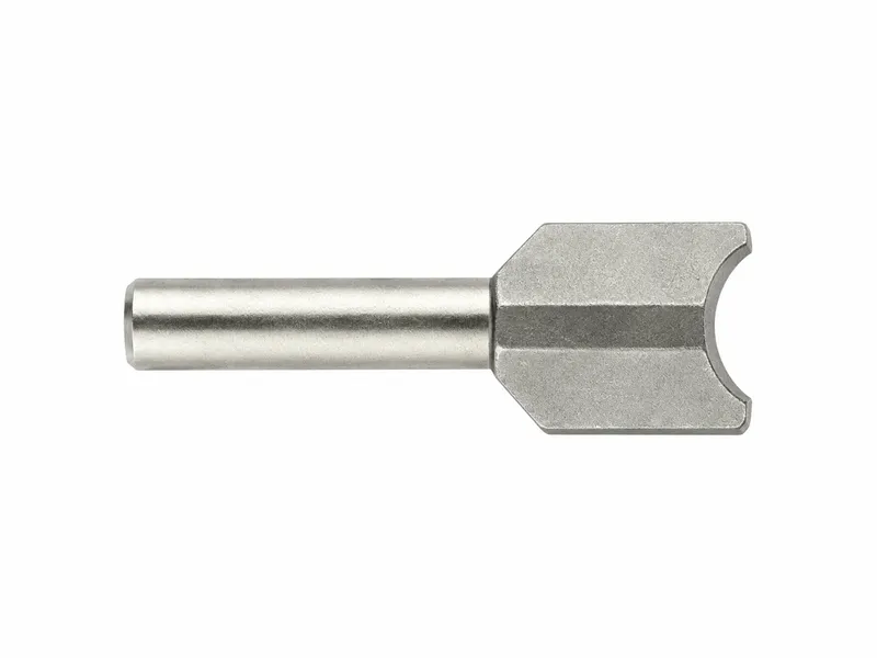
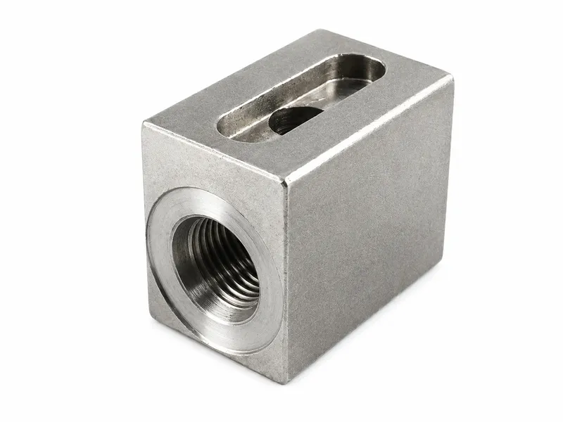
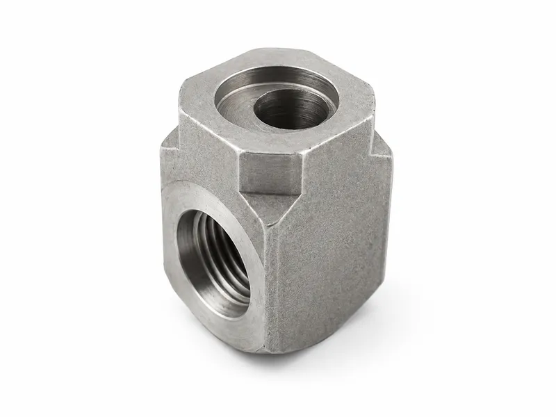
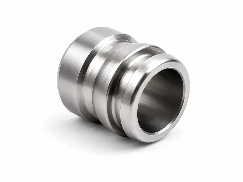
Custom turned, milled and combined-machining components manufactured from the latest approved drawing, model and project specification for hydraulic and industrial equipment.
Custom CNC parts are project-defined non-standard parts produced from the latest approved files and revision. If a 2D drawing, 3D model, specification, order or sample conflicts, the controlling document must be confirmed before production. Similar appearance does not establish equal material, tolerance, heat treatment, coating or function, and dimensional conformity alone does not validate complete-equipment pressure, load, fatigue, leakage, safety or life. Turning, milling, combined machining and drawing-specified secondary work can be reviewed; this page defines no uniform precision, minimum quantity, material range, lead time or performance.
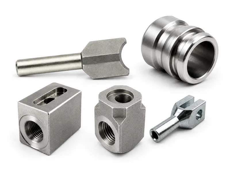
Wei Xing Machinery reviews made-to-drawing CNC parts as turned, milled, combined-machining or secondary-processed projects. Turned parts commonly contain diameters, bores, steps, shoulders, grooves, threads, tapers and faces. Milled parts commonly contain planes, pockets, slots, hole patterns, mounting faces, bracket forms and profiles. Turn-mill components combine these with drilling, boring, reaming or threading.
Grinding, honing, lapping, EDM, heat treatment, coating, welding, polishing, marking, assembly and cleaning are included only when specified and accepted after capability and order review. A sample may support visible-geometry review but cannot independently establish original dimensions, grade, treatment, hidden geometry, tolerances, function, load, pressure, life or acceptance criteria.
| Product Type | Project-defined, non-standard custom CNC parts manufactured to drawing; not a universal or stocked configuration. |
|---|---|
| Manufacturing Basis | Latest approved drawing and revision, approved 3D model where applicable, approved specifications and deviations, and confirmed purchase-order requirements. |
| Typical Machining Routes | CNC turning, milling, or turn-mill / combined machining selected by geometry and reviewed capability. |
| Document Control | Drawing, model, specification, order, approval date, superseded files, temporary deviations and engineering changes are revision-controlled. |
| Materials | Exact material grade and applicable standard are project-specific; this page does not define one material range. |
| Material Condition | Condition, temper, hardness condition and bar, tube, plate, forging, casting or extrusion form are confirmed. |
| Datums and Tolerances | Drawing-defined units, datum system, dimensions, general tolerance basis and GD&T; no category-wide tolerance applies. |
| Threads and Fits | Full thread designation, gauge or method, mating parts and drawing-defined clearance, transition or interference fits. |
| Surface Requirements | Surface parameter, lay, measurement direction, visual limits and functional surface requirements are confirmed by feature. |
| Heat Treatment | Only when drawing-specified and reviewed for material, hardness scale and range, treatment area, case depth, distortion and documentation. |
| Surface Finish | Material-compatible finish, masking, thickness, final-size basis, appearance and corrosion requirements are order-defined. |
| Secondary Processes | Drawing-specified grinding, honing, lapping, EDM, welding, polishing, marking, assembly or cleaning may be coordinated after review. |
| Inspection Basis | First-piece, in-process, final, sampling or feature-specific full inspection follows the agreed plan; a sample alone cannot define the original design. |
| Traceability Basis | Material certificates, heat records and lot traceability are available when specified and agreed in the order. |
| Prototype / Production Stage | Prototype, first article, pilot batch, production release and repeat order each require stage-specific confirmation. |
| Delivery Scope | Machined part plus only the treatment, records, marking, cleaning, protection, packaging and tests stated in the order. |
| Functional Validation | Part conformity alone does not establish assembly pressure, load, leakage, fatigue, safety, certification or service life; the complete assembly requires validation. |
| Applications | Hydraulic and industrial equipment projects subject to drawing, capability and project review; no universal certification is implied. |
Confirm drawing number, latest approved revision, approval date where applicable, dimensions, tolerances, GD&T, datums, threads, roughness, material, treatment notes and inspection requirements.
An approved model can define nominal geometry, surfaces, complex profiles, assembly position and machining references, but it does not replace drawing notes unless explicitly designated as controlling.
Confirm model, specification and order revisions plus material, processing, inspection, packaging, documentation and any approved deviation or concession.
If 2D, 3D, specification, sample or order information differs, identify the conflict, controlling file and approved correction before work proceeds.
| Control Item | What It Defines | Required Information | Inspection Consideration |
|---|---|---|---|
| Linear dimension | Feature size or location | Units, nominal and tolerance basis | Method matched to access and tolerance |
| Diameter | Shaft, bore or circular size | Size, limits and final condition | Micrometer, bore gauge or agreed method |
| Datum system | Reference frame for control | Primary, secondary, tertiary datum; axis, plane, target, origin or clocking | Simulate the drawing-defined datum; machining, inspection and functional datums may differ |
| Position | Feature location tolerance zone | Controlled feature, datums and material-condition modifier where applicable | Method and process stage defined by plan |
| Flatness | Form of one surface | Controlled surface and zone | Free-state or restrained-state condition where relevant |
| Parallelism | Orientation to datum | Datum and controlled feature | Fixture and datum simulation |
| Perpendicularity | 90-degree orientation to datum | Datum, feature and zone | Access and setup review |
| Roundness | Circular form | Section and controlled feature | Suitable form-measurement method |
| Cylindricity | Whole cylindrical form | Controlled cylindrical surface | Coverage and method appropriate to tolerance |
| Straightness | Line or axis form | Controlled element and condition | Support slender parts appropriately |
| Runout | Variation during rotation | Datum axis and surface; circular or total requirement | Rotation setup and datum alignment |
| Profile | Boundary of line or surface | Basic geometry, datums and zone | Comparison method suited to complex geometry |
Review shaft/bore, pin/bushing, bearing-seat, seal-groove, press, sliding and transition fits; thread engagement; locating shoulders; dowel interfaces; sealing and welding surfaces; fastener-preload interfaces; and assembly clearance. Request applicable mating bore, shaft, thread, seal, bearing, bushing, pin, fastener, fitting, valve, housing, bracket or welded-assembly data.
Confirm standard, nominal size, pitch or TPI, internal/external and hand, class, length, usable depth, runout, relief, lead-in, sealing function, mate and gauge or method. Diameter alone cannot identify metric, UN, BSPP, BSPT, NPT or another thread.
Distinguish total drill, full-diameter, drill-point, usable thread, tap, counterbore, spotface and functional bore depths. Review deep/cross holes for drift, intersection, wall section, chips, internal burrs, cleaning and inspection access.
Define coordinate or true position, pitch-circle diameter, angular spacing, pattern and datum relationships, orientation, counterbore, countersink, spotface and dowel holes. Inspection must suit the tolerance; a caliper is not sufficient for every pattern.
Separately define functional sharp, sealing, metering, handling, thread-start, intersecting-hole, weld-preparation, press-fit and unspecified edges, including break, chamfer, radius, burr direction/limit and inspection method.
| Surface Type | Possible Function | Information to Confirm | Common Risk |
|---|---|---|---|
| Sealing surface | Seal contact and leakage control | Parameter, lay, direction, waviness, defects and final condition | Marks or coating may affect sealing |
| Sliding surface | Guided relative motion | Roughness, lay, hardness, lubricant and mate | Wear, scoring or unsuitable lay |
| Bearing seat | Bearing location and support | Fit, form, finish, treatment and final size | Treatment distortion or incorrect fit |
| Press-fit surface | Retention by interference | Mating size, final finish, coating and assembly method | Coating or edge condition changes fit |
| Cosmetic surface | Visible appearance | Scratch, dent, tool-mark, discoloration and handling limits | Visual terms without an acceptance standard |
| Weld-preparation area | Joint preparation | Geometry, edge, cleanliness and post-weld machining | Distortion or contamination |
| Coated surface | Corrosion, appearance or other specified function | Coverage, masking, thickness, color and final-size basis | Buildup, exposed base metal or stains |
| Threaded surface | Fastening or drawing-defined sealing | Thread designation, finish, masking and gauge condition | Buildup and damaged starts |
Different surfaces need not share one requirement. A bright, mirror-like or smooth appearance does not replace a measurable specification. Confirm parameter, measurement direction, evaluation length, cutoff/filter when specified, lay, waviness, machining marks and visual limits. Coating changes the final surface; this page specifies no universal Ra value.
Confirm exact grade, standard, condition and raw-material form.
Confirm grade, heat-treatment compatibility, mechanical requirements and supply condition.
Confirm exact grade, condition, corrosion need, finish and magnetic requirements where relevant.
Confirm grade, temper, raw-material form, dimensional stability and compatible finish.
Review grade, condition, machinability, function and coating compatibility.
Review temperature, creep, moisture absorption, dimensional stability, machining and fit.
Confirm identity, quantity, condition, dimensions, allowance, defects, traceability, scrap, residual return and replacement responsibility.
Capability and compatibility are assessed against approved requirements; not every material is machinable for every project.
Through or case hardening, carburizing, nitriding, induction hardening, tempering, annealing, solution treatment, aging or stress relief is considered only when specified. Confirm material, area, scale/range, case depth, allowances, masking, distortion, final grinding, testing and records.
Suitable projects may specify zinc or zinc-nickel plating, black oxide or phosphate for steel; passivation/polishing for stainless; anodizing, conversion coating or paint for aluminum; or another compatible finish. Confirm area, masking, thickness, thread/seal/contact/weld/press-fit protection, color, appearance, corrosion and documentation.
Drawing-specified grinding, honing, lapping, wire or sinker EDM, welding, brazing, polishing, laser/mechanical marking, cleaning or assembly can be coordinated after capability, material and order review; not all work is performed in-house.
Confirm whether dimensions control before heat treatment/coating or in final treated condition, plus machining allowance and dimensional compensation. Treatment may distort parts; coating cannot replace correct material or structural design. No standardized hardness, case depth, thickness or salt-spray duration is offered. Welding requires joint, filler, heat input, distortion, post-weld machining, inspection and functional-validation review. EDM requires conductive-material, geometry, recast/heat-affected condition, finish and later-inspection review.
Wear, corrosion, deformation, coating loss, repairs, polishing, grinding, welding distortion, damaged threads, sealing damage or earlier modifications can obscure intent. The customer confirms reproduction authority, approved-sample status, wear restoration, mating data, function/safety responsibility and the final approved drawing.
| Stage | Primary Purpose | Required Approval | Key Risk |
|---|---|---|---|
| Prototype | Geometry, assembly, process or design review | Agreed prototype acceptance | Process may not represent frozen production |
| First article | Validate agreed dimensions, material, process and documents | Order-defined report/sample scope and customer disposition | Scope is not automatically a full FAI |
| Pilot batch | Pre-production machining, assembly and quality validation | Agreed batch and release criteria | Batch risks may differ from one sample |
| Production release | Manufacture from approved revision, frozen process and agreed plan | Documented release and acceptance basis | Unapproved changes or mixed revisions |
| Repeat order | Recurring manufacture after current review | Latest revision, order, deviation and scope confirmation | Old order data may be obsolete |
Available configurations depend on the approved drawing, material, dimensions, machining access, secondary processes, inspection and quantity. These descriptions do not imply stocked parts or direct substitutes.
| Manufacturing Route | Typical Geometry | Main Planning Focus | Information Required |
|---|---|---|---|
| CNC turning | Rotational diameters, bores, shoulders, grooves, threads, tapers and faces | Workholding, datum axis, length-to-diameter, runout and chip control | Drawing, material, diameters, lengths, fits, threads and quantity |
| CNC milling | Planes, pockets, slots, hole patterns, mounting faces, brackets and profiles | Access, setups, datum transfer, thin walls and internal radii | 2D/3D geometry, datums, hole data, finish and edge conditions |
| Turn-mill / combined machining | Rotational and prismatic features on one part | Sequence, clocking, datum relationships and inspection | Complete feature relationships and controlling model/drawing |
| Grinding or precision finishing | Drawing-defined final surfaces, bores or diameters | Allowance, treatment distortion, final datum and finish | Pre/final dimensions, material condition and inspection |
| EDM when specified | Conductive-material features selected after review | Access, recast/heat-affected condition, finish and later operations | Geometry, material, surface and inspection requirements |
| Machining plus welding | Machined features combined with specified joints | Preparation, heat input, distortion, post-weld machining and inspection | Joint, process, filler, boundary and validation requirements |
| Sample-based review | Visible geometry where approved data are incomplete | Wear, hidden data, assumptions and design authority | Sample status, mating data and final approved requirements |
CNC turning, milling and suitable turn-mill/combined machining; drilling, tapping, boring, reaming, counterboring, countersinking and spotfacing.
Internal/external threads, grooves, shoulders, slots, pockets, hole patterns, flanges, bores, cross/radial holes and complex profiles.
Feature-specific deburring, cleaning and marking when ordered.
Dimensional and thread inspection, plus drawing-specified surface-finish inspection using methods appropriate to feature, datum, access and tolerance.
Drawing-specified grinding, heat treatment, coating, EDM or welding may be coordinated after material, capability and order review.
Each part uses only applicable operations; capacity, process route and acceptance method are confirmed for the actual geometry and quantity.
Deep holes require review of access, drift, straightness, depth, intersection, chips, cleaning, inspection and adjacent walls. Thin walls, long shafts, plates and asymmetric parts require allowance, sequence, stress, fixturing, support and free/restrained inspection review because machining, treatment, welding, coating, clamping and storage may distort them.
Verify drawing/model consistency, numbers and revisions, material/condition, process plan and datums.
Define first-piece, in-process and final inspection plus sampling or feature-specific full inspection in the agreed scope.
Plan overall dimensions, diameters, bores, threads, hole positions, grooves, shoulders, fits and drawing-specified geometric tolerances.
Include surface finish, hardness or coating only when specified; review appearance, burrs, cleanliness, marking and packaging as ordered.
Material/treatment records, dimensional reports, retention and revision traceability are supplied when agreed; deviations require approval.
Calipers, micrometers, bore/height/thread/pin gauges, surface/hardness instruments, optical/profile methods, CMM or fixtures are selected only where appropriate.
Small tolerances require method, gauge resolution, repeatability, reproducibility, part/room temperature, fixturing, datum simulation, operator method and uncertainty review. Machine readout alone does not prove conformity. Functional pressure, leakage, load, torque, flow, fatigue, vibration, temperature or assembly testing is included only when the order defines the method and acceptance.
May include chip and loose-burr removal, washing, drying, passage cleaning or drawing-specified cleanliness.
Part number, revision, lot, material heat, serial/orientation or customer-specified marks are applied only when ordered.
May include individual, thread or sealing-surface protection, compatible VCI/oil, clean bags, partitions or export packaging.
Scope follows the order. Rust preventives must be compatible with later processes and media; no uniform cleanliness level, laser marking or individual package is assumed.
See related hydraulic valve bodies, valve spools and pistons, hydraulic manifold blocks, hydraulic cylinder parts, welded tube assemblies, hydraulic hose fittings and bulkhead connectors.
Automotive-related projects may be reviewed when drawing, material, traceability, inspection and project-specific requirements are clearly defined.
Wei Xing Machinery manufactures from customer-approved drawings, models, specifications, sample information and order requirements. The customer or design authority remains responsible for design, function, material selection, tolerance design, mating relationships, load, pressure and safety. We may provide manufacturability review but do not change the design without approval.
The customer confirms the controlling requirement when 2D, 3D, sample or order data conflict; worn sample dimensions are not automatically original dimensions, and customers should provide only files/models/samples they are entitled to use for manufacturing review. Part dimensional conformity does not validate complete-equipment pressure, load, fatigue, leakage or life.
Certificates, heat treatment, coating, welding, EDM, marking, assembly and testing must be stated in the order. First article, sampling, feature-specific full inspection and functional tests follow the agreed plan. Every deviation needs customer approval; final acceptance follows the approved revision and agreed inspection plan.
A custom CNC part is a project-defined, non-standard turned, milled or combined-machining component manufactured from approved drawings, models, specifications and order requirements.
At minimum, provide the latest approved 2D drawing and revision. A 3D model is recommended for complex geometry; also confirm material, quantity, tolerances, treatments, inspection and delivery requirements.
Work must pause while the controlling file, conflict location and approved correction are confirmed. The manufacturer must not choose the more convenient requirement.
A sample can assist visible-geometry review only. Approved information must confirm material, hidden features, tolerances, wear restoration, heat treatment, coating and function.
Materials and secondary processes are reviewed against the drawing, function, machinability, material compatibility and actual capability. Not every material-process combination is suitable.
They follow the approved drawing, datums, GD&T, function, quantity and agreed inspection plan. There is no uniform precision for the entire custom CNC parts category.
A prototype supports design or process review; a first article validates the agreed scope; production uses the approved revision and release conditions. Prototype approval does not automatically equal production approval.
Provide current drawings and revision, available model, function and mating data, exact material and condition, quantity and stage, tolerances/datums, thread and hole details, finishes, treatments, inspection, records, packaging and delivery requirements.
Submit the latest drawing and revision, available 3D model, part function, material, quantity, tolerances, secondary processes, inspection and documentation requirements for manufacturability review and quotation.