
Custom Hydraulic Hose Fittings
Hydraulic hose fitting components manufactured to customer drawings for crimped hose assemblies used in mobile machinery, industrial equipment and OEM fluid-power systems.
A hydraulic hose fitting is one component of a complete hose assembly. The hose, insert or stem, ferrule, retention geometry and crimp data must be confirmed as a compatible system; JIC, ORFS, BSP, NPT and metric equipment-side ends each use a separate sealing principle. This fitting page cannot define assembly pressure, temperature, bend radius or service life. Straight, 45° and 90° bodies, swivel nuts, one-piece or two-piece arrangements and different equipment ends can be machined to approved drawings. Wei Xing Machinery manufactures fitting components to those drawings and does not imply that an arbitrary hose-and-fitting combination has passed assembly validation.
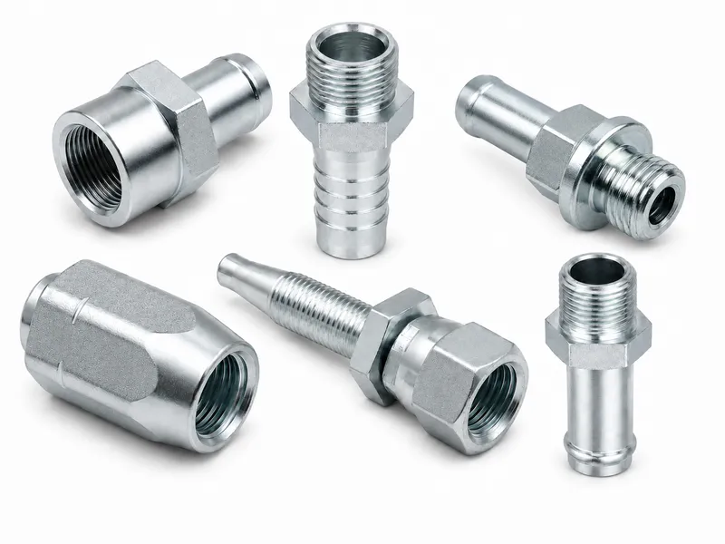
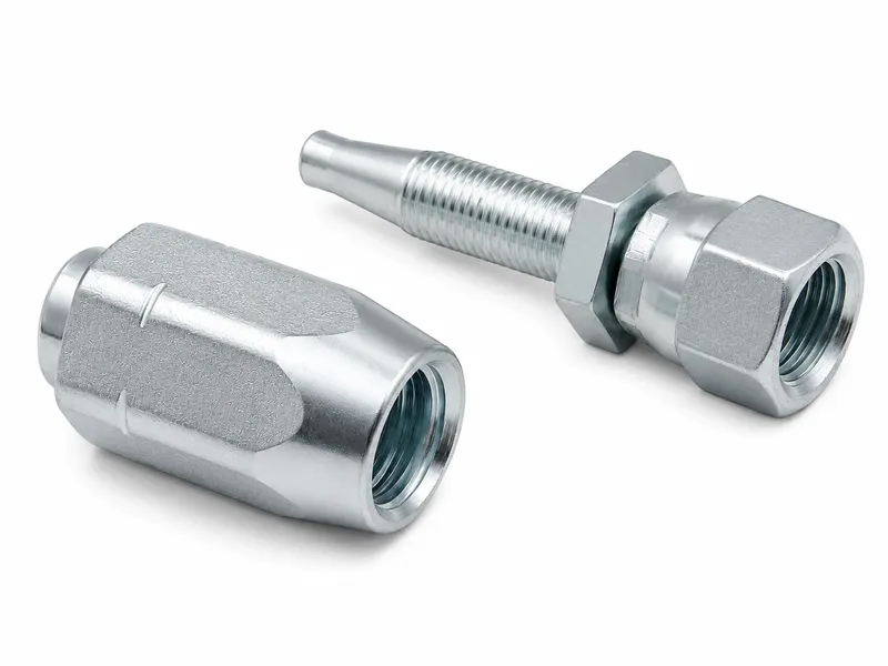
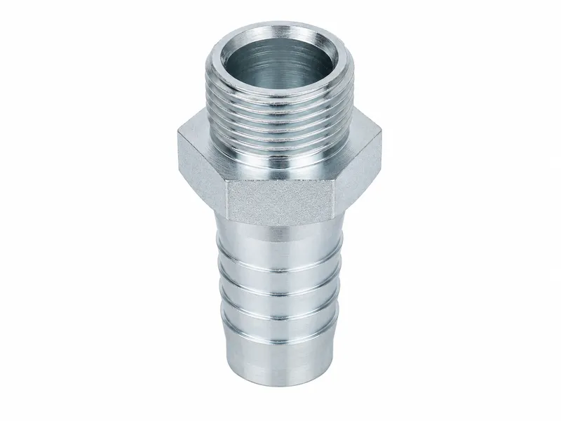
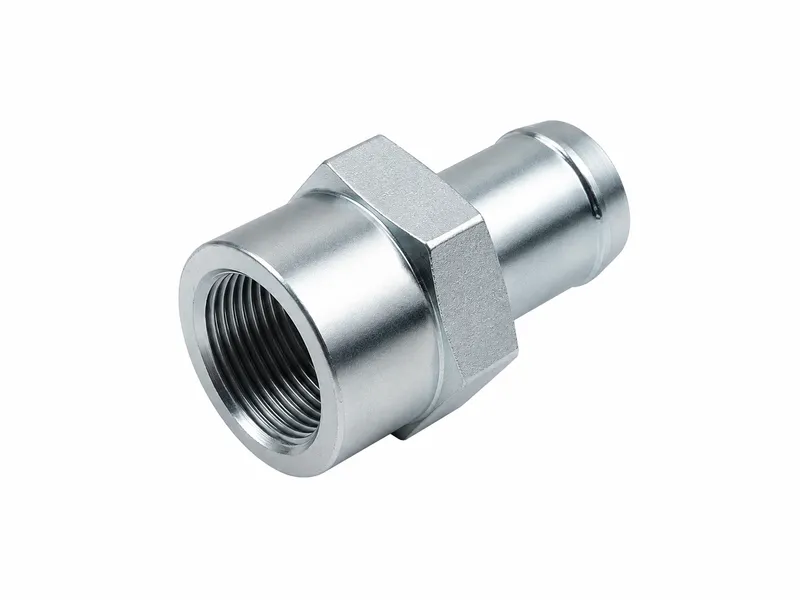
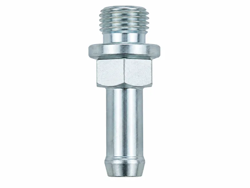
Hydraulic Hose Fitting Manufacturing
We manufacture custom hydraulic hose ends, stems, inserts and crimp ferrules to drawing-defined geometry. Reviews separate the hose-side retention system from the equipment-side connection and address material, finishing, inspection and production requirements.
Geometry may be reviewed against SAE J516, the applicable ISO 12151 series, or assembly guidance such as ISO/TS 17165-2 only when the approved drawing or order specifies it. Production follows the stated standard name and revision rather than a general website claim.
Key Specifications
| Product Type | Drawing-specific hydraulic hose fitting components that form part of a complete hose assembly. |
|---|---|
| Hose-Side Function | The hose, stem or insert, ferrule or socket, insertion and approved crimp structure work together for retention and sealing. |
| Equipment-Side Connection | JIC, ORFS, BSPP, BSPT, NPT, metric, flange or drawing-specific ends; sealing is confirmed independently. |
| Assembly Configuration | One-piece or two-piece systems; the arrangement does not automatically establish a performance level. |
| Hose Compatibility Basis | Exact hose series, construction, dimensions, cover, stem, ferrule and preparation method reviewed as one system. |
| Crimp Data Basis | Approved drawing, validated hose-and-fitting data, customer assembly specification or agreed validation plan; this page gives no general settings. |
| Body / Stem Materials | Carbon steel, stainless steel or other drawing-specified materials after media and application review. |
| Ferrule Materials | Drawing-specified steel or stainless steel; alternatives require hose-system and manufacturing review. |
| Surface Finish | Drawing- and material-specific coordinated finishing. |
| Manufacturing Basis | Approved 2D drawing, 3D model, dimensionally verified sample or order requirement. |
| Inspection Basis | Approved drawing and agreed sampling, full-inspection, documentation and test plan. |
| Pressure / Validation Basis | No category-wide rating. Complete assembly performance follows compatible parts, approved assembly data and validation requirements. |
| Applications | Mobile machinery, industrial equipment and OEM flexible hydraulic lines after system review. |
Hose Fittings as Part of a Complete Assembly
1. Hose
Confirm tube, reinforcement, inside and outside dimensions, cover and intended service.
2. Insert or stem
Use the profile specified for the approved hose and fitting system.
3. Ferrule or socket
Match its construction and identification to the stem and hose.
4. Preparation and insertion
Follow the defined cut, skive or no-skive method, cleanliness and insertion reference.
5. Approved crimp operation
Use qualified tooling, equipment condition, position, length and measurement procedure.
6. Equipment-side connection
Confirm standard, size, sex, sealing location, mate and assembly requirement.
7. Inspection and validation
Apply the agreed dimensional, assembly and testing plan.
8. Routing and installation
Avoid twist, abrasion, tension and sharp bends near the fitting; follow the hose routing specification.
Correct dimensions on one part do not qualify a complete hose assembly. Capability requires compatible components, approved assembly data, controlled equipment, inspection, specified testing and correct final installation.
Hose-Side Retention and Sealing
Defined component interaction
The insert enters the hose bore; the ferrule or socket is positioned outside the hose or as otherwise specified. The approved crimp process makes the specified components act together. Hose tube, reinforcement and cover construction therefore affect stem and ferrule design.
Process controls
Under-crimping or over-crimping can damage the hose, reinforcement, stem or ferrule. Incomplete insertion can reduce retention and sealing reliability; incorrect skiving can damage reinforcement, while burrs or sharp edges can harm the hose tube.
Skive or no-skive preparation is defined by the hose construction, fitting system, stem, ferrule, crimp specification and approved drawing—not selected at operator discretion.
Equipment-Side Connection and Sealing
| Equipment-Side End | Primary Sealing Location | Assembly Function | Information to Confirm |
|---|---|---|---|
| JIC 37° | 37° metal flare faces | Straight thread supplies clamping force. | Standard, size, sex, flare condition, mating end and torque procedure. |
| ORFS | O-ring against a flat face | Straight thread supplies assembly force. | Size, sex, O-ring material, groove, face and mate. |
| BSPP | Depends on end and port design | Parallel thread retains the specified sealing arrangement. | Seat, bonded seal, O-ring or other drawing-defined location. |
| BSPT | Taper-thread engagement with applicable sealant | Thread engagement provides the joint. | Thread designation, engagement, compatible sealant and port. |
| NPT | Taper-thread engagement with compatible sealant | Thread engagement provides the joint. | Designation, engagement, sealant, port and installation procedure. |
| Metric or drawing-specific | As defined by the approved drawing | Supports the specified mating interface. | Standard, revision, size, sex, seal, mate and assembly requirement. |
The hose-side crimp structure and the equipment-side sealing interface perform different functions and must be reviewed separately.
One-Piece vs Two-Piece Hose Fittings
| Feature | One-Piece Configuration | Two-Piece Configuration |
|---|---|---|
| Component arrangement | Ferrule is retained, preassembled or combined with the body for the product series. | Stem and ferrule are separately selected and assembled. |
| Ferrule handling | Reduced separate handling, but identification and inspection remain required. | Separate identification and pairing are required. |
| Hose-series dependence | Must match its approved hose series. | Each stem and ferrule must match the approved hose series. |
| Assembly tooling | Uses system-approved dies, crimper and procedure. | Uses system-approved dies, crimper and procedure. |
| Inventory identification | Identify the complete fitting series and revision. | Control stem and ferrule identities separately. |
| Validation requirement | Preassembly does not remove inspection or validation. | Complete selected combination requires validation. |
| Selection consideration | Neither arrangement is a universal high or low grade, and pressure cannot be chosen from the label alone. Do not mix stems and ferrules from different series. | |
Crimp Compatibility and Assembly Data
Component identification
Confirm hose manufacturer or approved specification, series, nominal size, outside diameter, stem series, ferrule series and equipment-side end.
Hose preparation
Confirm cut quality, specified skive or no-skive method, cleanliness, insertion depth and alignment.
Crimp process
Confirm approved specification, die set, calibrated crimper condition, tooling condition, method, operator procedure, measurement method, position and length.
Final assembly inspection
Check final dimensions, insertion reference, ferrule condition, exposed reinforcement, hose damage, twist, elbow clocking, cleanliness, thread and sealing surface.
Crimp outside diameter is not the only assembly parameter. This page does not provide machine settings; values must come from approved drawings, validated system data, customer procedures or an agreed validation plan.
Common Hydraulic Hose Fitting Types
- Straight, 45-degree and 90-degree hose fittings
- Female swivel and male fixed hose ends
- One-piece crimp hose fittings
- Two-piece inserts and ferrules
- Hydraulic hose stems or inserts
- Hydraulic crimp ferrules
- JIC, ORFS, BSPP, BSPT, NPT and metric hose ends
- Bulkhead-style and flange hose ends when specified
- Drawing-specific hydraulic hose connectors and components
Available configurations depend on drawing review, hose-system requirements, material, tooling and production requirements; this list does not imply stock availability. Swivel nuts primarily help alignment during installation and are not dynamic rotary joints. Angled ends require drawing-defined reference planes, relative clocking, assembly length, sealing-point length and clearance—never correct orientation by twisting the hose.
Hose Fittings vs Rigid Adapters and Tube Assemblies
| Connection / Product Type | Flexibility | Retention or Mounting | Fluid Sealing | Selection Considerations |
|---|---|---|---|---|
| Crimped hydraulic hose fitting | Part of a flexible hose assembly | Approved hose-side crimp system | Hose-side system and equipment end reviewed separately | Match hose, stem, ferrule, data and routing. |
| Reusable or field-attachable fitting | Part of a flexible assembly when specifically designed | Product-specific attachment | Per approved design | Use only where its design and approved procedure permit; do not treat it as an ordinary crimp fitting. |
| Rigid adapter | No flexible hose section | Threaded or otherwise drawing-defined connection | Interface-specific | Does not include hose-side crimp retention. |
| Bulkhead fitting | Fixed pass-through | Mechanical panel mounting | Each end confirmed separately | Confirm panel, nut, end interfaces and access. |
| Welded tube assembly | Rigid tube or welded construction | Supports and end connections | Weld and end-interface requirements | Does not provide hose flexibility. |
Hydraulic Hose Fitting Manufacturing Capabilities
Depending on the approved design, operations can include CNC turning; CNC milling where required; stem, insert, ferrule or socket profile machining; internal and external threads; sealing faces; specified 37° flare seats or noses; specified ORFS faces and grooves; taper threads; swivel-nut components; drawing-defined straight, 45° or 90° bodies; hex flats; drilling; boring; tapping; cross holes; insertion stops; crimp-zone dimensions; deburring; cleaning and dimensional inspection. Not every component uses every operation.
Surface finishing can be coordinated according to material and order requirements.
Materials and Surface Finishes
Bodies and stems
Carbon steel, stainless steel, or other materials subject to drawing, media and application review.
Ferrules
Drawing-specified steel or stainless steel; other materials require hose-system and manufacturing review.
Options may include trivalent zinc plating, zinc-nickel coating, black oxide, phosphating when applicable, natural stainless finish, and passivation when specified and material-compatible. A finish cannot replace correct material selection, hose compatibility, crimp design or equipment-side seal design.
Quality Control for Hose Fitting Components
- Drawing and revision review
- Hose-system and component identification
- Stem or insert profile inspection
- Ferrule inside/outside dimensions, length and crimp zone
- Specified insertion-stop position
- Hose-side edge and burr inspection
- Bore and flow-passage dimensions
- Equipment-side threads and sealing faces
- Applicable swivel-nut component fit and retention
- Elbow angle, reference orientation and overall length
- Hex flats, concentricity or specified alignment
- Material, documentation, finish appearance and cleanliness
- Protective caps when specified
- Sampling or full inspection according to the agreed plan
Proof, leak, burst, impulse, pull-off, retention, dimensional qualification or assembly qualification testing applies only when the approved drawing, order or validation plan specifies it. A metal fitting alone does not establish complete hose-assembly test performance.
Applications
- Mobile construction machinery
- Agricultural machinery
- Forklifts and material-handling equipment
- Industrial machinery
- Hydraulic power units
- Hydraulic cylinders and actuators
- Pump, valve and manifold hose connections
- OEM hose assembly programs
- Custom flexible hydraulic lines
- Maintenance and replacement projects based on verified data
For replacement work, verify the original hose, end connections, assembly length, orientation and application conditions; do not copy only the appearance of an old fitting.
Information Required for Quotation
“1/2-inch hydraulic hose fitting” alone is not enough for an accurate quotation. At minimum, identify the exact hose series, inside and outside dimensions, reinforcement, preparation, stem and ferrule series, crimp data, equipment end, angle, orientation, material and application.
- 2D fitting drawing and 3D model when available
- Approved sample with verified dimensions
- Fitting components or complete hose assembly scope
- Hose manufacturer or approved specification and series
- Nominal size, inside diameter and outside diameter
- Reinforcement construction and hose cover
- Specified skive or no-skive preparation
- Insert/stem and ferrule/socket series
- Approved crimp data and insertion depth when available
- Equipment-end standard, size and male/female form
- Swivel requirement and straight, 45° or 90° body
- Angular orientation and assembly length when applicable
- Material, surface finish and quantity
- Fluid, fluid/ambient temperature and exposure
- Pressure or validation requirements
- Routing, movement and installation conditions
- Inspection, testing and documentation requirements
- Packaging requirements
Engineering and Validation Responsibility
- Wei Xing Machinery manufactures fitting components to customer-approved drawings, models, verified samples and order requirements.
- The customer, hose-assembly manufacturer or system designer confirms compatibility among hose, stem, ferrule, crimp parameters and assembly process.
- The customer or system designer confirms complete-assembly pressure, temperature, media, bending, routing, dynamic duty and system validation.
- Sample appearance alone cannot define internal stem profile, crimp dimensions, material, tolerances, standard revision or assembly capability.
- Hoses and fitting parts from different manufacturers or series must not be mixed without technical review, confirmed assembly data, samples, applicable validation and approval.
- Crimper, dies and measurement method must follow the approved assembly procedure.
- A swivel nut is not a dynamic rotary joint.
- Final acceptance follows the approved drawing and agreed inspection plan.
Crimped hose-end components must not be assumed reusable. Reuse is permitted only when the specific design and approved procedure explicitly allow it; inspect deformation, threads, sealing faces, corrosion, cracks, coating damage and contamination after removal.
Frequently Asked Questions
What is a hydraulic hose fitting?
A hydraulic hose fitting is a component of a complete flexible hose assembly. Its hose side connects through a specified retention system, while its equipment-side end mates and seals according to the selected interface.
Which components must be compatible in a crimped hose assembly?
The hose, insert or stem, ferrule or socket, preparation method, insertion depth, crimp parameters and equipment-side connection must be confirmed as one compatible system.
Is nominal hose size enough to select a hose fitting?
No. Selection also requires the exact hose series, inside and outside diameters, reinforcement construction, skive requirement, stem and ferrule series, and approved crimp data.
What is the difference between one-piece and two-piece hose fittings?
A one-piece configuration has a ferrule retained, preassembled or combined with the fitting for its product series. A two-piece configuration uses a separately selected stem and ferrule. Neither establishes a pressure class without system compatibility and validation.
Can hose fittings and ferrules from different systems be mixed?
Not by matching size alone. A non-original combination requires technical review, drawing and assembly confirmation, samples, an applicable validation plan, and approval by the customer or system-responsible party.
Does a swivel nut rotate continuously during operation?
No. A swivel nut primarily helps connection alignment during installation; it is not a dynamic rotary joint designed for continuous rotation under pressure. Hose twist must still be avoided after installation.
How is the pressure capability of a hydraulic hose assembly determined?
The complete assembly must use mutually compatible components and approved assembly data. Allowable conditions are determined by the validated assembly specification, the limiting component or interface, and the agreed validation requirements—not by a webpage for one metal fitting.
What information is required to quote a custom hydraulic hose fitting?
Provide a drawing or verified sample, exact hose specification and dimensions, stem and ferrule details, approved crimp data, equipment-side interface, orientation, material, finish, quantity, operating conditions, and inspection or testing requirements.
Related Technical Guides
Use these guides to identify and compare the equipment-side interface on a hydraulic hose fitting.
Send Your Hydraulic Hose Fitting Drawing for Review
Submit the fitting drawing, hose series, hose dimensions, insert and ferrule details, approved crimp data, equipment-side connection, material, quantity and application requirements for manufacturing review and quotation.